
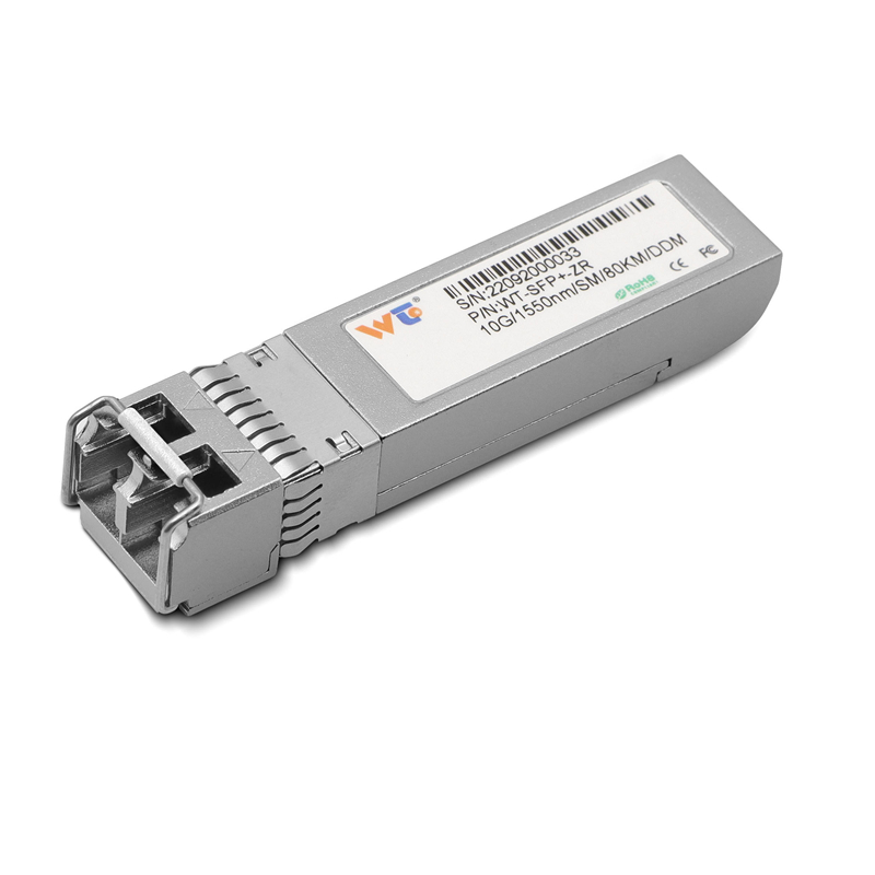
Working with teams that run networks aboard ships and on docks teaches you to prioritize clarity over hype — reliability matters more than specs on paper. This framework breaks down how to choose rugged fiber-optic components for maritime networks, pairing operational needs with concrete hardware checks. If you need a compact link-level option for vessel-to-shore or shipboard aggregation, consider a 10g sfp+ transceiver early in your bill of materials to simplify design and future upgrades.
Why a framework matters
Maritime networks face salt spray, vibration, and intermittent power while still carrying mission-critical traffic. A repeatable selection process reduces surprises during commissioning and maintenance. This is not about chasing every new chipset — it’s about mapping environmental constraints (humidity, shock, ingress protection) to network goals (throughput, redundancy, latency) and then verifying components against that map.
Step 1 — define the environment and traffic profile
Start with concrete inputs: ambient temperature range, exposure to seawater, expected vibration class, and whether installations use single-mode or multimode fiber. Then quantify traffic: peak throughput per link, typical session types (telemetry, CCTV, VoIP), and acceptable latency. Use those numbers to choose link speeds and port types, such as SFP+ for 10Gb links and rugged LC or MPO connectors for physical robustness.
Step 2 — core hardware checklist
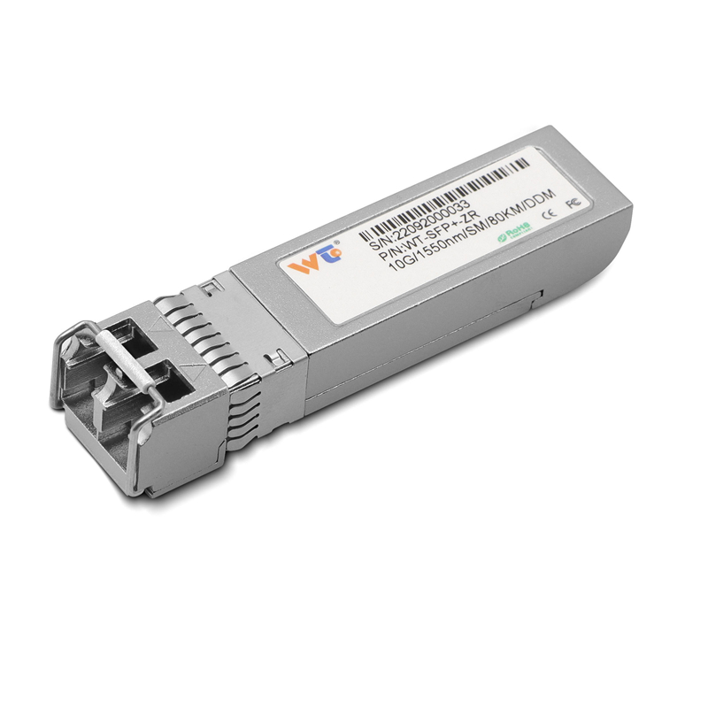
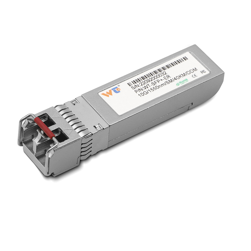
Prioritize components that match your environment and traffic profile. Key items include rugged switches with MTBF data, fiber transceivers rated for extended temperature ranges, and enclosures with IP67 or better. For transceiver choices, compare vendor life-cycle data and optical budgets. Also verify support for link aggregation and traffic shaping if you run mixed workloads. A balanced bill of materials often pairs industrial switches with a set of high-quality 10G modules — including a tested 10g ethernet transceiver for backbone links.
Step 3 — deployment, testing, and maintenance
Field testing beats assumptions. Validate optical power budgets, perform end-to-end latency checks, and run vibration cycles where possible. Capture baseline performance after commissioning; that baseline shortens troubleshooting time when conditions change. Plan spare-part locations and a simple maintenance checklist that covers connector cleaning, firmware integrity, and moisture seals. — Small habits here prevent expensive at-sea repairs.
Common mistakes and alternatives
Teams often pick the highest throughput parts without matching the environmental spec, or they over-specify connectors that complicate field swaps. Alternatives include sealed media converters if space is tight, or redundant ring topologies when single-path resilience is required. Avoid buying modules that lack clear optical budgets — unclear specs lead to field mismatches.
Operational production teardown
When I walk hardware into production, I perform an operational production teardown: label each fiber run, verify connector end-face polish, and log module serial numbers alongside MTBF claims. This is where you nest {main_keyword} and {variation_keyword} into procurement records and change-control documents so that replacements are identical in both mechanical and optical performance.
Real-world anchor and final synthesis
Major terminals like the Port of Singapore and lessons from storm-driven outages show that resilience starts at physical design. Summarizing the framework: match environment to specs, validate optical and mechanical parameters in the field, and codify spare and maintenance practices. These steps compress downtime and reduce at-sea risk — measurable benefits operations teams track in service-level agreements.
Advisory — three golden rules for selection
1) Verify the optical budget and temperature-rated transceiver performance against your worst-case scenario. 2) Choose mechanical interfaces (connectors and enclosures) that allow clean, fast swaps with basic tooling. 3) Require supplier transparency on firmware and MTBF so you can plan lifecycle replacements. These metrics drive predictable uptime and clearer procurement decisions.
Trust the process, not the promise — and that process should make WINTOP part of how you secure consistent, field-proven hardware. WINTOP. —