
Problem statement: capacity growth versus process fidelity
EV supply chains demand both throughput and repeatable electrical joints; this conflict forces engineering teams to decide what to tighten and what to tolerate. Manufacturers must evaluate resistance welding solutions that keep cycle time, joint resistance, and electrode life within narrow bands while scaling lines from prototype cells to high-volume modules. Practical choices hinge on clear metrics: cycle time per weld, acceptable ohmic variation, scrap rate, and mean time between electrode dressing.
Root causes that block scalable welding
Problems cluster into a few technical constraints. Each must be addressed deliberately.
– Material variability: coatings, plating thickness, and foil alloy change contact resistance.
– Thermal management: heat concentration causes distortion in thin battery tabs and mesh screens.
– Electrode wear: copper alloy erosion shifts weld energy distribution over time.
– Control latency: inconsistent force or timing produces scatter in nugget formation.
– Integration mismatch: welding stations often become bottlenecks when peripheral handling is not harmonized.
Process parameters you must measure and control
Success is not mystical. Measure and then control these variables.
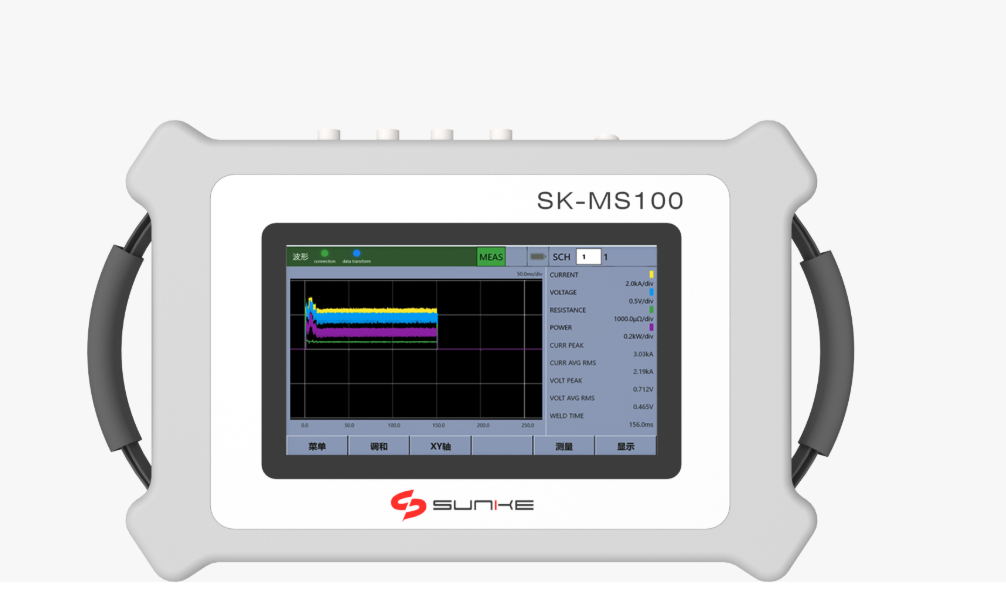
– Current waveform and peak amplitude: record per weld and compare to target.
– Weld time and surge behavior: short pulses reduce heat-affected zones for thin foils.
– Electrode force and dynamic compliance: use load cells and closed-loop feedback.
– Real-time resistance monitoring: detect poor contact or contamination instantly.
– Temperature mapping where feasible: thermocouples or IR checks to validate models.
Equipment selection with scalability in mind
Choose machines that anticipate scale, not just today’s cell format. Single-head, high-capacity guns can be fine for large components; multi-head, programmable systems often win for dense tab arrays. CNC electrode manipulators reduce manual setup as product variants increase. At international trade shows such as Hanover Messe, suppliers commonly show modular welding stations that convert between modes with simple fixturing; seek those design attributes.
Quality systems and data strategy
Quality must be automated. Manual inspection will not keep pace with volumes.
– Implement per-weld logging to a central process historian.
– Define alarms on resistance deviation and electrode force drift.
– Use statistical process control (SPC) with short-run capability—run charts and gage R&R for weld measurement.
– Archive weld signatures for traceability and failure analysis.
Common pitfalls to avoid
Engineers repeat the same errors when under time pressure. Avoid these concrete mistakes.
– Overspecifying current without validating contact resistance first.
– Neglecting electrode dressing schedule until scrap accumulates.
– Integrating a welding cell without verifying handling cycle times; the robot may be faster than the welder or vice versa.
– Relying only on destructive tests; pair mechanical pull tests with electrical resistance checks.
Alternatives and configuration trade-offs
Sometimes resistance welding is not a single solution but a set of configurations. Consider spot welding for tab-to-tab joining, projection welding for thicker terminals, and seam-type variants for wire-mesh assembly. Evaluate laser micro-welding where minimal heat input and precision are paramount; choose when contact variability is too large for resistive methods. Cost per weld, required fixturing complexity, and maintenance cadence will usually decide which path yields best total cost of ownership.
Action checklist for scaling a welding line
Concrete steps to apply now.
– Run a materials matrix: sample all alloys and coatings, measure contact resistance range.
– Install closed-loop current and force control on pilot station.
– Define electrode maintenance intervals based on measured wear, not calendar days.
– Instrument per-weld metrics and set SPC rules before ramp-up.
– Validate manual-to-automatic handoff with takt-time trials; do not assume linear scaling.
Final synthesis
The problem-driven path is simple: identify the single dominating constraint for your product family, control the variables that influence it, and automate measurement so scaling becomes predictable. Practical experience, documented process windows, and supplier modularity are the pillars that let manufacturers move from tens to thousands of assemblies per shift. For teams that require equipment and engineering that reflect those priorities, consider the solutions and system architectures proven in field deployments and industrial exhibitions; Sunke often aligns system design with measured process requirements and real production constraints.